DIY line following Robot(Kits)

Brief introduction of working principle:
LM393 to compare two photosensitive resistance, when the imbalance (e.g. side pressure runway black) immediately control side of the motor stops rotating, the other side of the motor rotational acceleration, so that the car modification direction, return to the correct direction, the whole process is a closed loop control therefore, rapid and sensitive control.

Assembly steps:
The first step: the circuit part of the basic welding
The welding circuit part is relatively simple, the welding sequence according to the element height from low to high, the first 8 resistance welding, welding must use a multimeter to confirm whether the correct welding resistance, polar components such as transistors, green lights, be sure to clear electrolytic capacitor polarity as the reference element we picture welding, welding capacitor short is the negative side of the insertion pin PCB screen printing shadow, green welding LED note long pin is positive, and the welding time is not too long or easy to bad welding, D4 D5 R13 R14 can temporarily not welding, the integrated circuit chip can be inserted, preliminary after completion of welding please check carefully to prevent, be negligent.
Second step: mechanical assembly
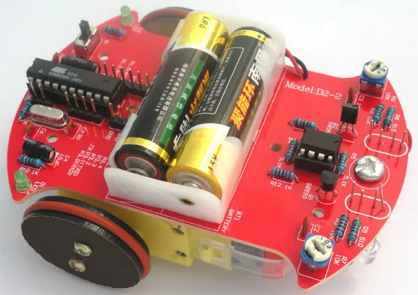
The universal wheel screw is inserted into the PCB hole, and screwed into the universal wheel nut and a universal wheel. The battery box is posted on PCB by double-sided adhesive, lead wire through the PCB reserved Kong Han received PCB on the red to the 3V positive power supply, yellow line grounding, the excess wire can be used for motor connection.
Mechanical part and assembly can be assembled first wheels, wheel is composed of three pieces of black acrylic round tablets, assembly prior to protective film to expose, the inside of the wheel center hole grows circular hole, in the middle of the round plate diameter is relatively small, lateral wheel piece center hole Shiyuan, with two screw nuts fixed set good three round tablets, and black self tapping screws fixed on the rotating shaft of the motor. Finally, the silicone rubber tire sleeve on the wheel. Lead connection lead wire of the motor and the wheel assembly is the use of the adhesive on the PCB making position, pay attention to wheels and the PCB edge preserving sufficient clearance, the motor leads are soldered to the PCB. Note that appropriately to stay longer lead, to prevent the motor direction of rotation error is convenient for changing the lead wire of the order.
The third step: the installation of photoelectric circuit
A photosensitive resistor and a light emitting diode (note the polarity) is reversely installed on the PCB, and the ground distance of about 5 mm, between the photosensitive resistor and a light emitting diode is about 5 mm in distance. The electricity can be tested.
The fourth step: Vehicle debugging
In the battery box into 2 AA batteries, switches to dial in the "on" position, the car right driving reverse is traveling along the direction of the universal wheel, if hold down the left side of the photosensitive resistance, the car on the right side of the wheel rotation, press and hold the right of photosensitive resistance, the left side of the car wheel should turn, if car back traveling can exchange connection of two motors simultaneously. If one of the normal back on the other side, as long as the exchange of the back side of the motor wiring can be.
Note:
Assembly instructions is the back of the car tracking the airstrip, customers can also direct use of 1.5 ~ 2.0 cm black electrical tape pasted directly designed to track complex on the ground would be more fun.