MA12070 Audio Amplifier Board 2*80W stereo class D Amplificador

Infineon MA12070 high-end digital power amplifier product.
Main product features:
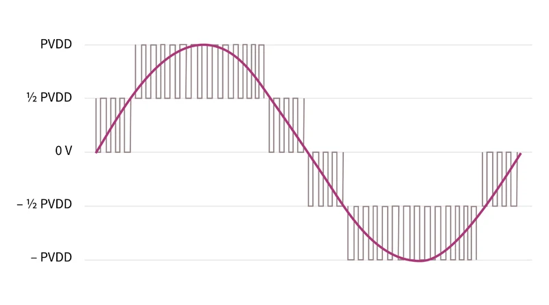
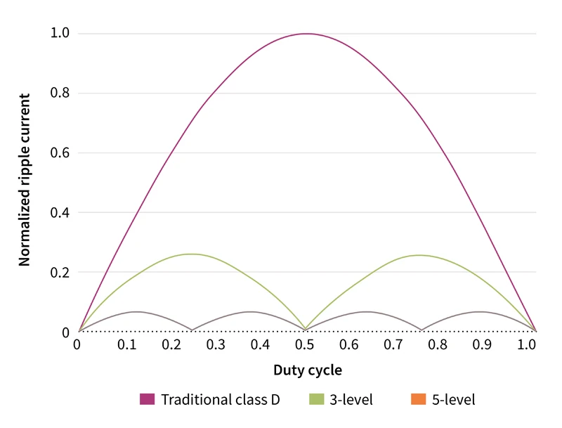
1. Multi-level switching technology with 3-level and 5-level modulation makes the solution unparalleled in power consumption and energy efficiency-optimized for power consumption during music playback, making it extremely low energy consumption.
2. 2×80W peak output power (26V PVDD, RL = 4Ω, 10% THD+N level)
3. Flexible realization of 2.0 (2*80W), 2.1 (1*80W+2*40W), 4.0 (4*40W), 1.0 (1*160W) channel output level configuration through the on-board DIP switch.
4. The fourth-order feedback error control can provide better gain and suppress errors better than the traditional second-order loop, thereby ensuring extremely low signal distortion and excellent audio performance, even if the power supply is not ideal (noise or ripple) Wave), still ensuring low distortion, high sound quality and stability and reliability.
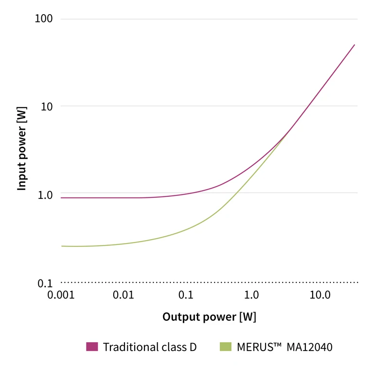
5. <160mW idle power dissipation (26V PVDD, all channels are switched); when the power is 2W, the efficiency is >80% (1kHz sine wave, 8Ω); when the power is full power, the efficiency is >91% (1kHz sine wave, 8Ω).
6. Audio performance (PMP2): >110dB SNR (A-w, relative to 1% THD+N power level), without the need for complex dynamic follow-up power supply design (conventional audio power design solutions that improve energy efficiency).
7. 45μV output integrated noise (A-w), no low-pass filter (LPF) is required in most applications.
8. When the output level is high, THD+N is 0.004%.
9. I2C control (four optional addresses on the dial switch on the board), can be connected to the MCU to control the working mode of the chip, balance performance and power consumption, and can be customized in various applications.
10. Built-in protection: undervoltage lockout, overheat warning/error, short circuit/overload protection, power stage pin to pin short circuit, error report via serial interface (I2C), and DC protection.
11. Four-layer immersion gold PCB + anodized heat sink, with excellent heat dissipation and extremely low EMI.
12.Length: 80mm, Width: 60mm, Height: 35mm
Application
1. Portable speakers-battery powered speakers, mobile Bluetooth speakers, docking speakers, portable speakers, wearable speakers
2. Home audio-multi-room system, TV, sound column, home theater system, independent components
3. Voice control speaker
4. Professional audio-active monitor speakers, Power over Ethernet (PoE), multi-channel system


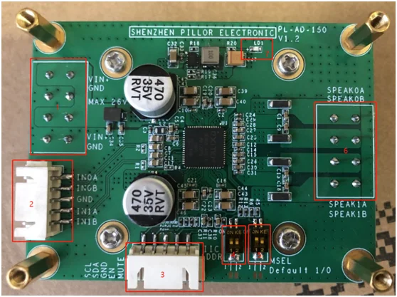
1. DC power input terminal. The interface sequence from top to bottom is: VIN+, GND, VIN+, GND, two VIN+ and two GND are connected on the board to facilitate module cascading. The maximum input voltage of VIN+ is DC +26V, and the absolute voltage exceeding +27.5V will permanently damage the chip To ensure the output power, please use a power supply of 200W and above. The minimum input voltage of VIN+ is +4V, and it is actually recommended to use a power supply above 6V.
2. Analog audio signal input terminal. The interface sequence from top to bottom is: IN0A, IN0B, GND, IN1A, IN1B, corresponding to the audio input terminals of SPEAK0A, SPEAK0B, SPEAK1A, and SPEAK1B respectively. The overall board gain is 20dB by default.
3. External control communication input terminal. The interface sequence from left to right is: SCL (clock pin of IIC), SDA (data pin of IIC), GND (ground), EN (the chip enters the reset state when pulled high), MUTE (mute output, pull low) effective).
4. IIC address selection pin, used to control multiple chip selection IIC addresses when multiple modules are used in parallel. Bit 1: AD0, bit 2: AD1.
5. Chip working mode selection. Bit 1: MSEL1, Bit 2: MSEL0. (Push up means 1)
Bit1/Bit2=0/0: 4-channel single-ended output (SE), at this time the maximum output power of each channel is 40W. The connection method is shown in the figure below:
Bit1/Bit2=0/1: 2 channels of single-ended output (SE) + 1 channel of half-bridge output (BTL), at this time, the power of each channel of single-ended output is 40W, and the power of half-bridge output channel is 80W. The connection method is shown below:
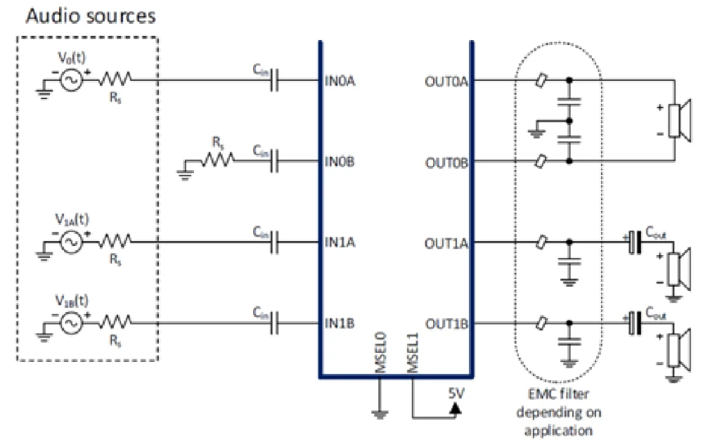
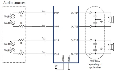
Bit1/Bit2=1/0: 2-channel half-bridge output (BTL), at this time, the output power of each channel is 80W (factory default setting). The connection method is shown below:
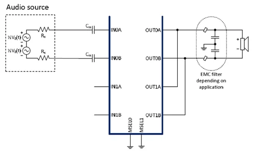
Bit1/Bit2=1/1:1 channel dual half bridge output (PBTL), at this time, the single channel output power is 160W. The connection method is shown in the figure below:
6. Audio power level output terminal. The interface sequence from top to bottom is: SPEAK0A, SPEAK0B, SPEAK1A, SPEAK1B.
7. Power indicator LED. Green or blue LED, this LED should always be on after power on, indicating that the power supply of the module is normal.
Module use steps
1. Correctly set the DIP switch at position 5 and correctly connect the speaker hardware.
2. Set the voltage correctly at the 1 interface and connect the DC power supply, you can see the LED at position 7 is lit.
3. Connect the input audio source to the 2 interface correctly.
4. Other parts generally do not need to be connected to work normally.
Note: PCBs for subsequent shipments are all black, and there is no longer a green PCB version.


PCB size: 100X60MM
Supply voltage: AC15-32VX2
Impedance range: 4-8 ohm
Distortion: <0.05%
Power: Rated 100WX2
Channel: 2.0 channels
Feature:
1. 100% Original TDA7293
2. PCB is double-sided gold, better conductive properties and sound quality
3.The main capacitor is 3300UF Black D-iamond or P-anasonic 4PCS.
4. The input coupling is ERO or VIS capacitor with fine natural sound quality.
5. The board comes with a soft-start circuit to start up without impact. Public version of circuit design, stable and reliable
(The main capacitor position is compatible with 4x18MM diameter filter capacitors or 2x25MM diameter filter capacitors