4S 40A/60A/80A smart baord LiFePO4 BMS/PCM/PCB battery protection board for 4 Packs 18650 Battery Cell with balance function, with temperature switch, with APP,
Note: this BMS with balance function. your battery need match, battery should have good consistency, if not sure, please use new brand battery.
the board not include USB and Bluetooth moduel.
the USB to serail module and Bluetooth need buy separately.
USB to serial module or Bluetooth should use together with the board.
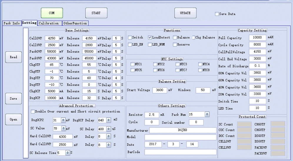
USB to serial module connect to PC by USB, so you can monitor the board, and set the parameter.
Bluetooth module can connect to smart phone, right now only support android 4.3 above.
APP support english
about software, please contact seller.
after order, seller will give you APP link.
Features:
1) high-accuracy voltage detection circuit;
2) terminal of the charger using high voltage device;
3) Built-in three-stage over-current detection circuit (over-current 1, over-current 2, or load short circuit);
4) MOS transistor can control the battery charge and discharge;
5) low standby current consumption.
6) with UART interface, Bluetooth interface, support PC or smart phone.
7) over charge and over discharge can set by software( APP).
40A/60A/80A, share the same board, the difference is the MOSFET. 80A version, all MOSFET installed.
40A version: continuous work current: 40A, over current: 80A
60A version: continuous work current: 60A, over current: 120A
80A version: continuous work current: 80A, over current: 160A
80A version Parameter:
charge voltage: 3.65V *4 = 14.6V
continuous work current: 80A
over charge: 3.6~4.3V
over discharge: 2.0~3.3V
balance voltage: 3.3~4.2V
balance current: 50mA
parameter can set by software(APP).
Notice:
1) Please note that the input and output voltage, and load current conditions for power protection board does not exceed the electrical parameters of the allowable power consumption;
2) special attention to the load current can not work long hours between maximum continuous operating current and over-current protection current;
3) When connecting the battery ,it may not discharge. In this case, connect the charger can be restored to normal working condition;
4) Although the BMS built-in electrostatic protection circuit, but please do not hand touch when BMS in the working condition, so as to avoid damage from static electricity protection board.
5) If the picture is not the same as the parameters,please check according to the parameters table.
wiring diagram
charge: B+ and C-
discharge(load) : B+ and C-
Wiring sequence: First solder line B- to battery negative, connect balance cable to battery(B1 B2 ... B4), after check the voltage is ok, then insert the cable(socket), After check, then connect C- line, then look at the amount of the total voltage of the battery, if the voltage between C- and B+ equal the total voltage, it’s should be work properly.
step 1: connect battery, check carefuly
step 2: plug the balance cable, first low bit ( BC0), last high bit.
windows PC software DEMO
SMT Workshop:
